
The coordinates may be precise. The reference framework tells us what they mean.
Most people looking at a map never ask what it is referenced to.
They see roads, property lines, utilities, contours, buildings, aerial imagery, perhaps a blue dot showing where they are standing. If everything appears to line up, the natural assumption is that everything belongs together.
Most of the time, for ordinary purposes, that assumption works well enough.
But in surveying, engineering, construction, floodplain work, utilities, LiDAR, GIS, and digital twins, there comes a point when “it looks like it lines up” is no longer enough.
WHAT IS THIS INFORMATION REFERENCED TO?
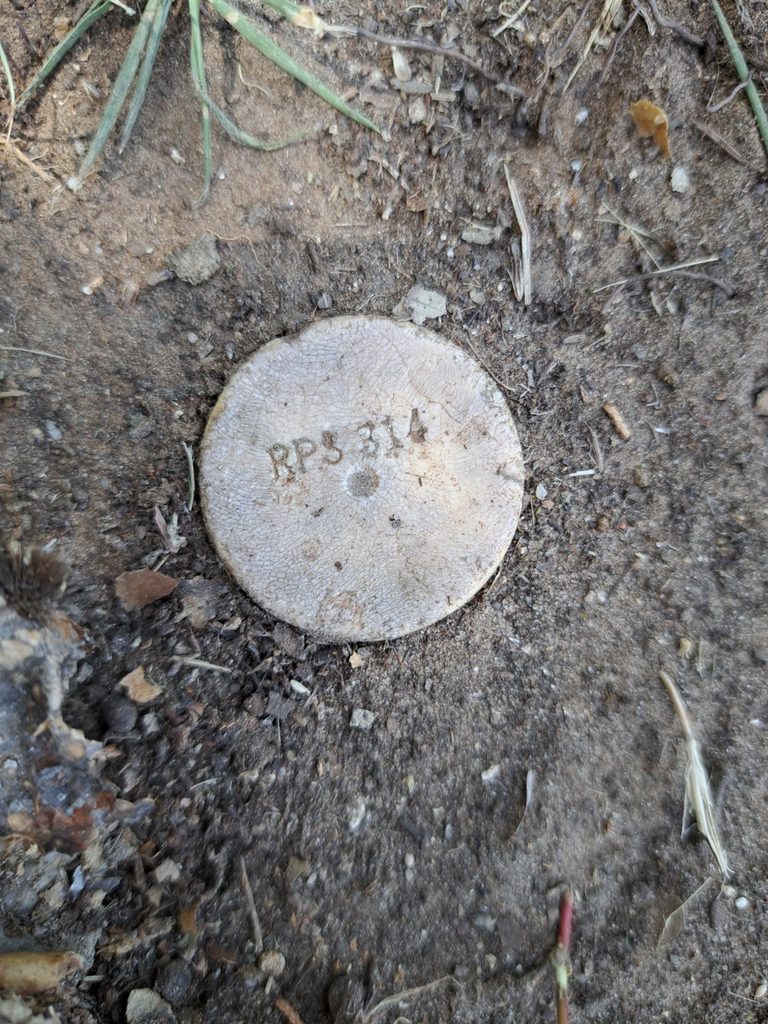
Figure 1. Point 201—a 5/8-inch capped iron rod recovered at the Somervell County Amphitheater boundary. The cap is stamped RPLS 314.
On the boundary surrounding the Somervell County Amphitheater, our crew recovered Point 201—a 5/8-inch capped iron rod stamped RPLS 314. The physical monument, the field record, the survey drawing, and the coordinate file each preserve a different part of the work.
The photograph shows what the crew found. The field book records the observation. The survey drawing relates that evidence to the rest of the boundary. A coordinate file describes its measured position.
CENTRAL IDEA: The coordinate does not create the corner. But if someone must reproduce, integrate, or rely upon that coordinate, we need to know what it is referenced to.
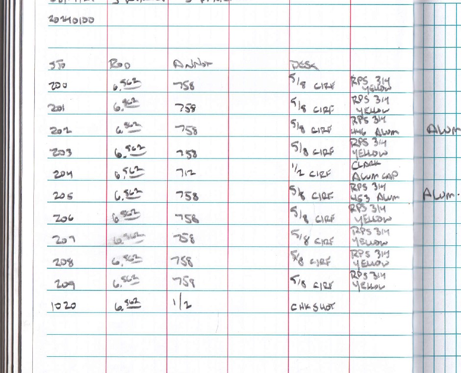
Figure 2. TTSM field-book entry for Point 201: a 5/8-inch capped iron rod found, stamped RPLS 314, with a yellow cap. The field record preserves what the crew actually observed.
What Does Point 3’s Coordinate Mean?
Point 201 is a recovered boundary monument. Point 3, from the same project, served as ground and scanning control. Its coordinates show the reference-system question more clearly:
POINT 3 — N 6,779,562.664 | E 2,199,955.333 | ELEV. 797.805
Those numbers look precise. They carry three decimal places. But without the reference framework, another professional does not have enough information to reproduce or use the position reliably.
What coordinate system? What zone? What datum or reference frame? What units? Is the elevation orthometric or ellipsoid height? Was a localization applied? Are the values grid coordinates, ground coordinates, or an assumed project system?
The control file identifies Point 3 as a magnetic-nail ground-control and scanning-control point. The survey notes provide the rest of the framework: Texas State Plane Coordinate System, North Central Zone 4202, NAD 83 (2011), with elevations referenced to NAVD 88 using GEOID18.
The technology may give us the number. The surveying process tells us what the number means.
A Datum Is the Starting Framework
The National Geodetic Survey describes a geodetic datum or reference frame as an abstract coordinate system with a reference surface that provides known locations from which surveys and maps can be created. In the United States, the National Spatial Reference System supplies the national framework for position, height, scale, gravity, and related geospatial information.
Surveyors have dealt with reference systems for generations, even as the terminology and technology changed. When I started surveying, the crew was more likely to think in terms of a known monument, benchmark, bearing basis, recorded survey, or assumed coordinate. Today a GNSS receiver may connect us almost instantly to a much larger geodetic framework.
That is extraordinary progress. But the principle remains familiar: we still need somewhere to start from.
Then We Put the Curved Earth on a Flat Drawing
The earth is not flat. Our CAD drawing usually is. A map projection converts positions on the curved earth into coordinates we can work with on a plane. The State Plane Coordinate System was developed to support surveying, engineering, and mapping throughout the United States.
Here in North Central Texas, many projects are referenced to the Texas State Plane Coordinate System, North Central Zone. That recognized framework lets surveyors, engineers, GIS professionals, contractors, and owners exchange information instead of everyone creating unrelated coordinates.
But saying “State Plane” is not enough. Which zone? Which datum and realization? Which units? Are the distances grid or ground? Those details may seem small until datasets from different sources have to fit together.
NIST retired the U.S. survey foot for new applications beginning in 2023, while preserving it for historical and legacy use. Texas Natural Resources Code §21.077 defines both U.S. survey feet and international feet. That is one more reason to verify the units when working with older State Plane coordinates.
We Put This Information on Our Surveys for a Reason
The amphitheater survey notes state that bearings and distances are correlated to the Texas State Plane Coordinate System, North Central Zone 4202, NAD 83 (2011). Elevations are correlated to NAVD 88 using GEOID18. The drawing also identifies grid distances and its scale factor.
Most clients probably look first at the boundary, buildings, easements, parking, roads, and aerial photograph. But those few lines of notes provide something essential: they tell another professional what framework supports the measurements.
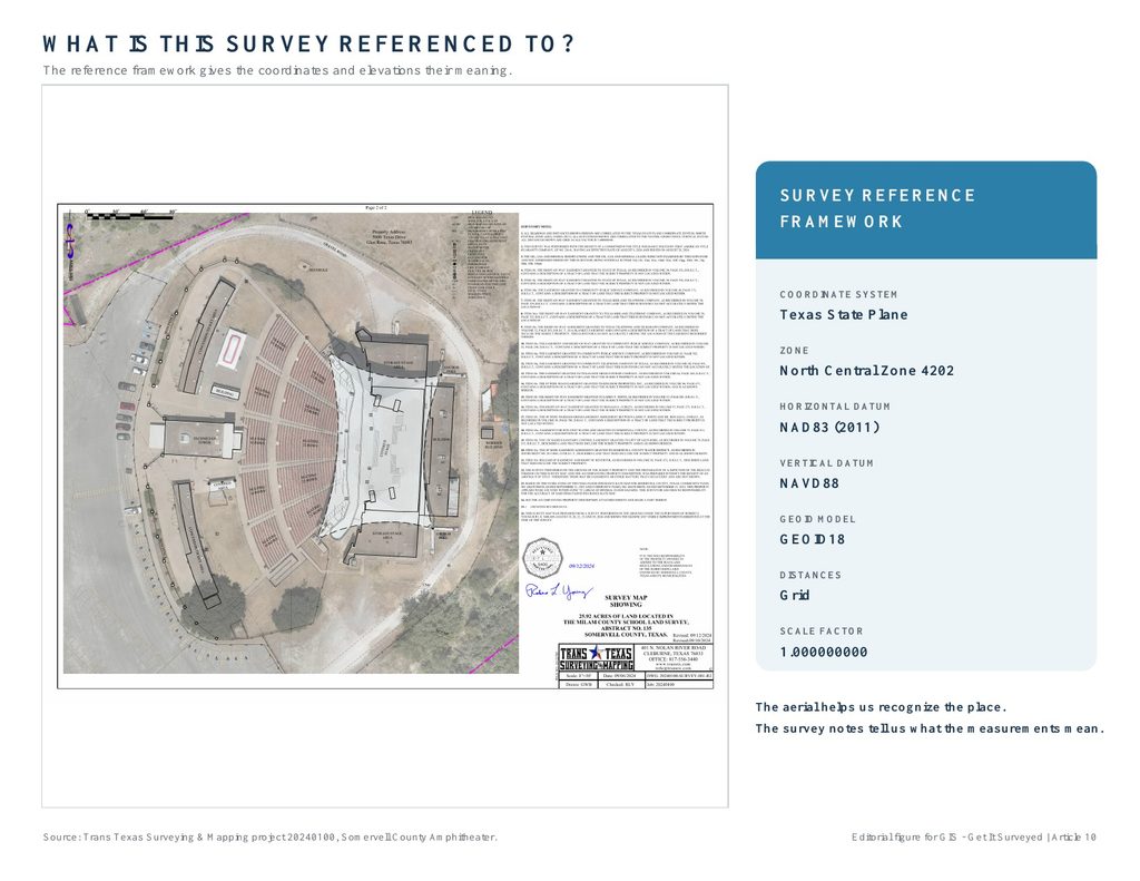
Figure 3. The aerial helps us recognize the place. The survey notes document the horizontal and vertical reference framework that gives the measurements meaning.
The Control File Connects the Work
This same project used ground-control and scanning-control points. The following excerpt shows how a simple coordinate record connects physical marks, aerial mapping, scanning, and the finished survey.
| Point | Northing | Easting | Elevation | Description |
|---|---|---|---|---|
| 3 | 6,779,562.664 | 2,199,955.333 | 797.805 | MAG GCP / Scan Control CP1 |
| 4 | 6,779,363.234 | 2,200,014.064 | 796.764 | MAG GCP / Scan Control CP2 |
| 5 | 6,779,429.820 | 2,200,173.572 | 788.025 | GCP / Scan Control CP3 |
| 6 | 6,779,750.433 | 2,200,242.098 | 784.812 | GCP / Scan Control CP4 |
| 7 | 6,779,704.194 | 2,199,969.279 | 795.748 | MAG GCP / Scan Control CP5 |
Excerpt from 20240100-CONTROL.TXT. PNEZD values are shown in U.S. survey feet under the documented project reference framework. (MAG = magnetic nail; GCP = ground control point.)
Reading a U.S. survey-foot northing of about 6.78 million as international feet displaces the point by roughly 13.6 feet in northing alone. With the easting error included, the combined horizontal displacement is about 14.3 feet. The monument has not moved; the coordinate units were misread.
These points are useful because we know what they are tied to, what they were used for, and how to reproduce the relationship.
Horizontal Is Only Half the Story
Elevation creates even more confusion. If somebody tells me a point has an elevation of 742.35, I want to know: 742.35 based on what?
A vertical datum establishes the reference from which elevations are measured. For this project, the vertical datum is NAVD 88. As of October 2026, NGS is still testing the modernized National Spatial Reference System through beta products; those products are not yet the official operational reference for this work. The project’s documented datum—not a newer name on a software menu—governs how these elevations should be understood.
GNSS also produces ellipsoid height—a height relative to a mathematical ellipsoid. That is not automatically the orthometric elevation most people mean when they ask, “What is the elevation?”
For compatible NAD 83 (2011), epoch 2010.0 work in the conterminous United States, GEOID18 is the NGS hybrid geoid model used to relate ellipsoid heights to NAVD 88 orthometric heights.
An elevation needs a reference too.
The Wrong Elevation Can Still Look Reasonable
A bad horizontal coordinate may place a feature somewhere obviously wrong. A bad vertical reference can be harder to recognize. An elevation such as 702.46 looks reasonable. The terrain may look reasonable. Nothing flashes red on the screen.
But was it NAVD 88? NGVD 29 (the older National Geodetic Vertical Datum of 1929)? An assumed construction datum? GNSS ellipsoid height? A local benchmark labeled 100.00? Was the proper geoid model used? Was a benchmark transferred from another project phase?
Until we know the reference, we do not really know what 702.46 means. For drainage, floodplain relationships, finished floors, rail platforms, gravity sewer, and structural elevations, that distinction can matter considerably.
Floodplain and Construction Work Make the Point
In a recent Burleson floodplain scope, we specifically established NAD 83 / Texas State Plane North Central horizontally and NAVD 88 / GEOID18 vertically. The entire assignment involved comparing surveyed ground with flood-related information. A contour labeled 720 and another elevation labeled 720 are not automatically equivalent simply because the numbers match.
Construction projects can also use local or assumed systems successfully. There is nothing inherently wrong with BM #1 = 100.00. The problem begins when nobody documents that it is assumed, and a later survey referenced to NAVD 88 is imported beside it. The lines appear close, the elevations differ, and someone starts moving data to make it fit.
The problem is not that every project must use the same coordinates. The problem is not knowing which coordinates we are using.
GIS Makes Reference Systems Invisible
Modern GIS can often transform information between coordinate systems automatically. That is tremendously useful. It is also why users may not realize how much is happening behind the screen.
A parcel layer may come from one source, aerial imagery from another, LiDAR from another, utility data from another, and survey control from another. GIS may display them together even though they did not begin in the same reference system.
Coordinate transformation can place datasets in the same reference framework. It cannot manufacture accuracy that was not present in the source data.
The Same Point Can Have More Than One Correct Coordinate
One monument is one physical object, yet it may legitimately have several coordinate descriptions: latitude and longitude, Texas State Plane northing and easting, a local construction coordinate, or a coordinate from an older datum or realization.
Those values may all describe the same monument within their respective systems. To compare them intelligently, we need to know each coordinate’s reference frame, units, epoch when relevant, and any transformation used.
WGS 84 is not a magic label. Many consumer mapping and GPS products use WGS 84-based geographic positions, while this project uses NAD 83 (2011) State Plane coordinates. Software can transform between properly defined systems, but a familiar-looking location on a screen does not make the reference frames identical.
NGS distinguishes WGS 84 from NAD 83 and other terrestrial reference frames. GEOID18 is intended for NAD 83 (2011), epoch 2010.0 ellipsoid heights—not indiscriminately for WGS 84, ITRF, or another frame.
The Field Crew Is Part of the Reference System
Coordinate systems do not exist only in software. The framework ultimately connects to something observed: a monument, benchmark, GNSS control point, reference station, project network, backsight, level loop, localization, or check shot.
Our crews verify the correct project, coordinate system, datum, zone, units, pole height, corrections, and RTK fixed-solution (FIX) status before accepting GNSS observations. A fixed solution is not a substitute for checking the project control. Field control checks and office comparisons occur before the information becomes a deliverable.
Check the Control Before You Stake Anything
More than once, we’ve arrived to stake a railroad or construction project and discovered that the elevations we were given did not agree with the control on the ground. In some cases, the discrepancy involved GNSS ellipsoid heights being used where elevations tied to the project’s vertical datum through a geoid model were expected. The difference was far beyond anything acceptable for construction staking. For perspective, a geoid height of −26.6 meters represents roughly 87 feet of separation between compatible ellipsoid and orthometric heights. The actual value varies with location and the geoid model. A discrepancy of that size is a reason to check the vertical reference—not proof of what caused the error.
We don’t start setting stakes just because somebody gave us a coordinate file. We check into control first—even when it’s our own control. If something doesn’t agree, we stop and investigate. We check the vertical reference, geoid model, benchmarks and field observations. Sometimes that means going back into the field and observing points again.
I tell young surveyors to verify their control every day they return to a project. Check into known points and make independent measurements. With GNSS, repeat observations in different sessions and under different satellite configurations when appropriate. Don’t assume yesterday’s good measurement guarantees today’s setup.
A consistent wrong answer is still wrong. Before we stake somebody else’s design, we need to know our control is sound and our measurements are referenced correctly. That’s how we protect the client, the contractor and the work we put our name on.
Do Not Fix It in CAD
When two datasets do not align, the first reaction should not be to move one until it looks right. We should determine why they do not align.
Wrong coordinate system? Wrong zone? Different datum? Different units? Grid versus ground? Local calibration? Incorrect base point? Wrong geoid model? Old control? Drafting error? Or do the datasets represent different physical information?
Moving a dataset may make the picture look better while destroying the evidence that could have explained the problem.
Never transform, scale, rotate, localize, or “fix” field coordinates in CAD without documenting what was done and preserving the original field export.
GIS and Surveying Become Stronger Together
GIS professionals work with coordinate reference systems. Surveyors work with control, datums, projections, monuments, benchmarks, GNSS, and field measurements. These disciplines meet at the reference framework.
Survey information must be documented well enough to integrate correctly. Surveyors increasingly need to understand how their data will move beyond the survey drawing into GIS, engineering, asset management, machine control, point clouds, digital twins, and systems we may never see.
The farther the information travels, the more important its reference information becomes. Coordinate system, datum, units, control source, vertical datum, geoid model, and transformation history are part of the deliverable—not trivia in small print.
Before You Trust the Coordinate, Ask What It Means
- What coordinate system is this in?
- What datum or reference frame?
- What zone and units?
- What is the vertical datum and geoid model?
- What control established it?
- Were transformations or localizations applied?
- Can the reference be independently reproduced?
- Is the framework appropriate for the decision we are about to make?
Sometimes a GIS-grade position is exactly what we need. Sometimes an assumed coordinate system is completely appropriate. Sometimes a phone GPS position is plenty good enough. Sometimes we need a defined national reference system, project control, benchmarks, and independent checks.
The answer depends on the purpose. But before we trust the number, we should know what gives the number meaning.
WHERE DID IT COME FROM? | WHAT IS IT REFERENCED TO? | CAN SOMEBODY REPRODUCE IT?
And when the answer matters enough:
GET IT CONTROLLED. GET IT SURVEYED.
Technical Sources
- NGS — Datums and Reference Frames — accessed October 17, 2026
- NGS — GEOID18 Overview — accessed October 17, 2026
- NGS — GEOID18 Technical Details — accessed October 17, 2026
- NGS — State Plane Coordinate System — accessed October 17, 2026
- NGS — Modernized NSRS Timeline — accessed October 17, 2026
- NGS — September 2026 modernization beta release — accessed October 17, 2026
- Texas Natural Resources Code §21.077 (units of measurement) — accessed October 17, 2026
- NIST — U.S. Survey Foot FAQ (unit definitions) — accessed October 17, 2026
Project sources: TTSM Survey Project 20240100; field book 288, pages 62-64; 20240100-CONTROL.TXT; 20240100-SURVEY-001-R2 aerial and linework deliverables.
Robert L. Young, RPLS 5400 | Trans Texas Surveying & Mapping | www.transtx.com
GIS — Get It Surveyed™ | A Robert L. Young Educational and Book Series
© 2026 Robert L. Young. All rights reserved. Reproduction or distribution requires written permission, except as permitted by law.